 Pусский
 English
 Français
 Español
 Portugues
 Deutsch
 lingua italiana
 العربية
 Melayu
 Filipino
 Монгол хэл
 dansk
dansk Bahasa indonesia
 日本語
日本語 한국어
한국어 Türk dili
 Tiếng Việt
 svenska
 Nederlands
 Norsk språk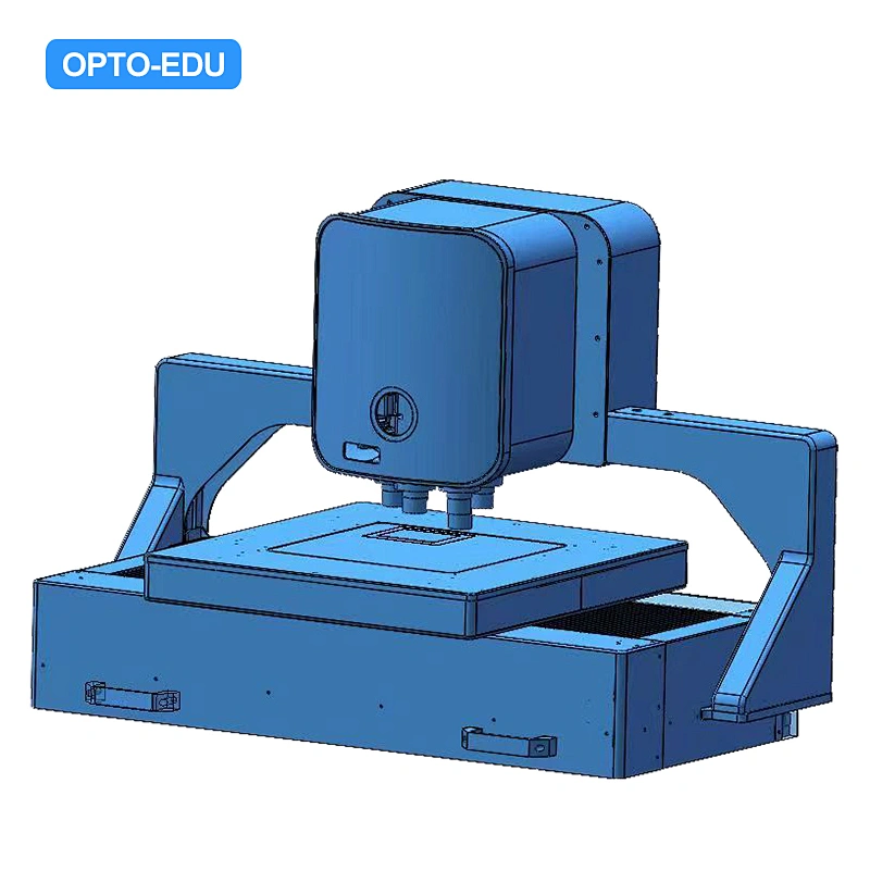

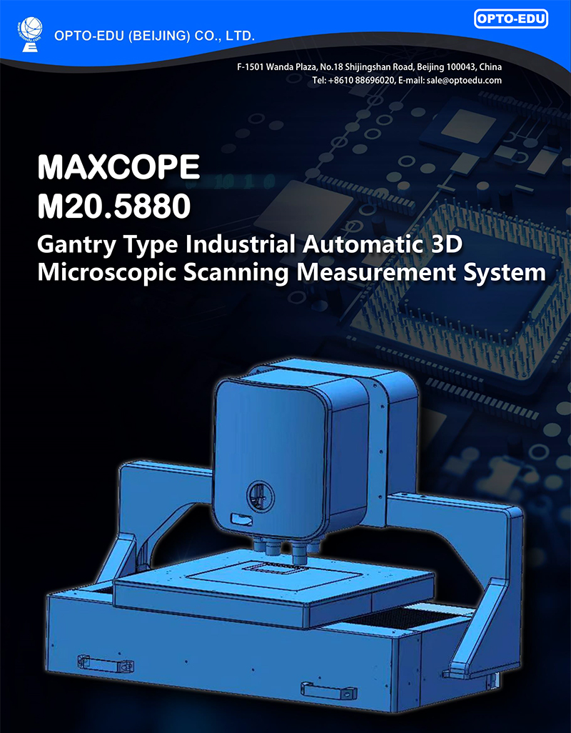
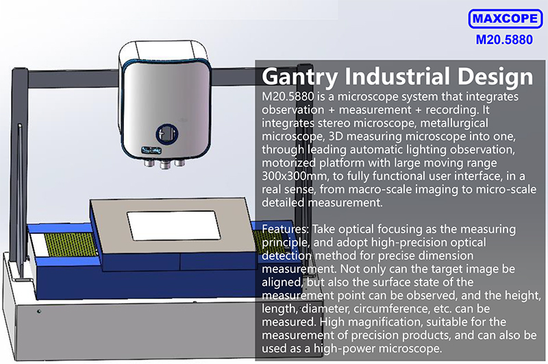
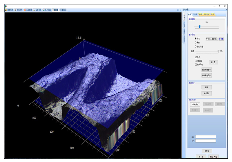
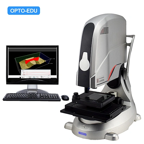
| MAXCOPE 3D Full Auto Scanning Measurement System The new M20.5880 Research-grade Metallurgical Microscope has upgraded to XYZ motorized working stage model, combined with the powerful Maxcope 2D/3D software, which integrates a number of firsts. From appearance to performance, it closely follows the international leading design trend. MAXCOPE will continue to provide customers with complete 3D industrial inspection solutions. |
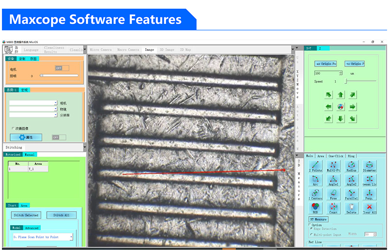
| XY Motorized Control Control the motorized stage through software, support one-click set/return to origin point, Long press the mouse and drag in the camera preview window to control the electric platform to move in the corresponding direction |
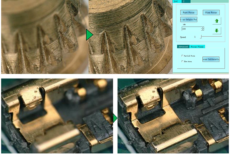
| Z Motorized Control The software controls the Z-axis motorized lift, support professional functions such as manual focus/auto focus/super depth of field fusion, create 3D image for view & measurement |
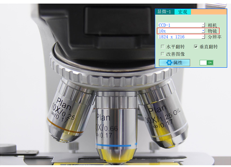
| Motorized Nosepiece Optional motorized nosepiece models, you can select different objective lenses in the software, and switch the magnification with one key |
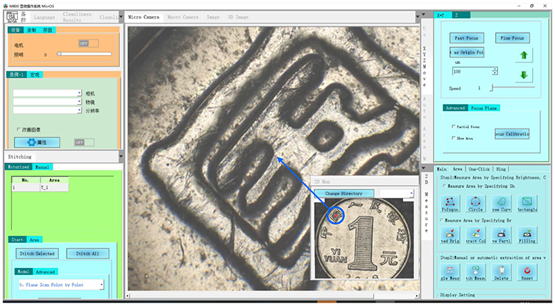
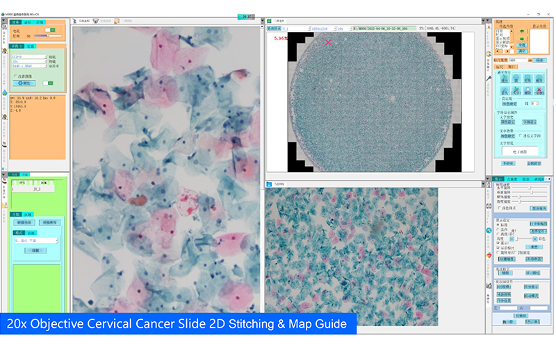
| 2D Map Guide After scanning and stitching to generate a panoramic image, it can be used as an electronic 2D map for navigation. Click the 2D map to control the motorized stage to quickly locate the specified position for high-magnification observation |
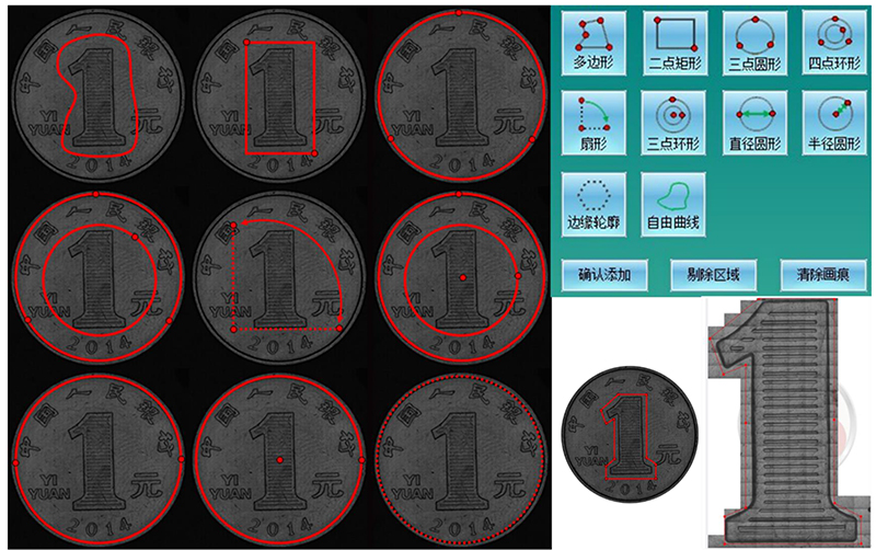
| Free Stitching Area 10 stitching area modes can quickly set stitching areas of any shape. Outline mode can automatically detect the edge contour of the object as the stitching area. |
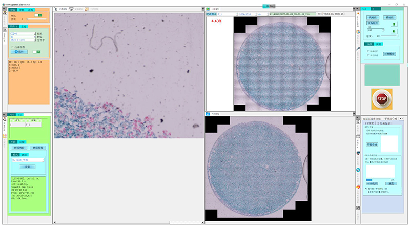
| Stitching Optimize The built-in advanced algorithm can intelligently optimize and correct the grid phenomenon and shadow phenomenon caused by lens aberration, uneven lighting and other factors when scanning and stitching, so that the stitched image will be one high-definition, no offset, no grid, no shadow. |
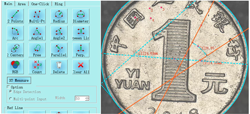
| 2D Measurement 10+ Functions, including length, angle, radius, diameter, free curve length, radius, diameter, arc length, RGB measurement, counting, etc., and a variety of auxiliary lines and reference line tools are provided. |
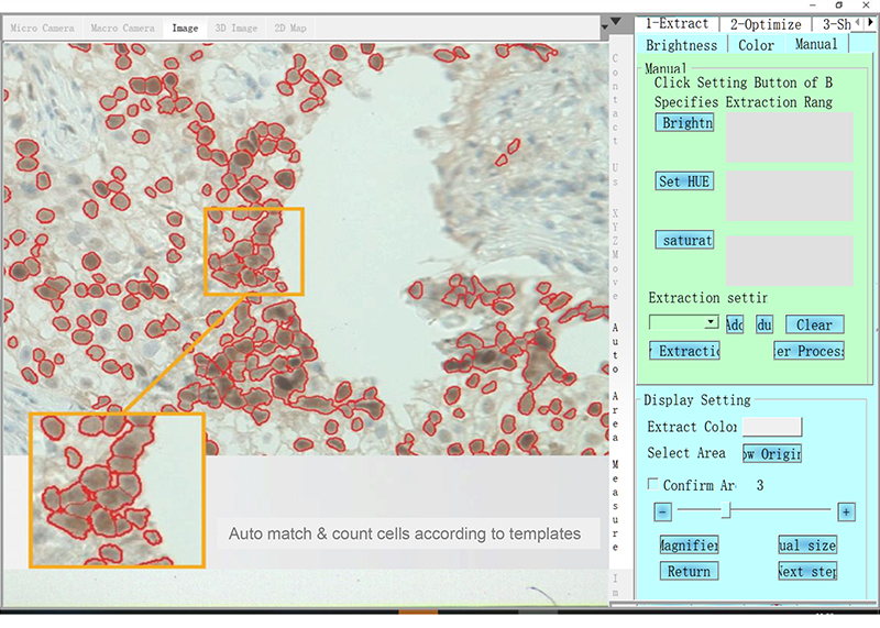
| One Click Auto Measurement Multiple measurement items can be saved as templates, software intelligently matches similar shapes, removes redundant targets or separates overlapping targets, automatically performs unified measurement, counting and analysis for multiple targets by one click |
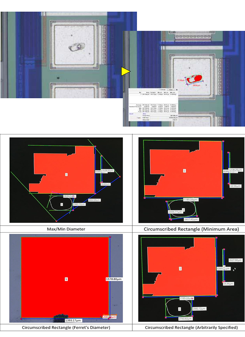
| Max Area Measurement Just use the mouse to specify the measurement range, the software automatically detects the edge of the object and selects the measurement area, you can add or delete measurement areas at will, and measure the largest area of any complex shape by automatic edge recognition instead of manual precise positioning |
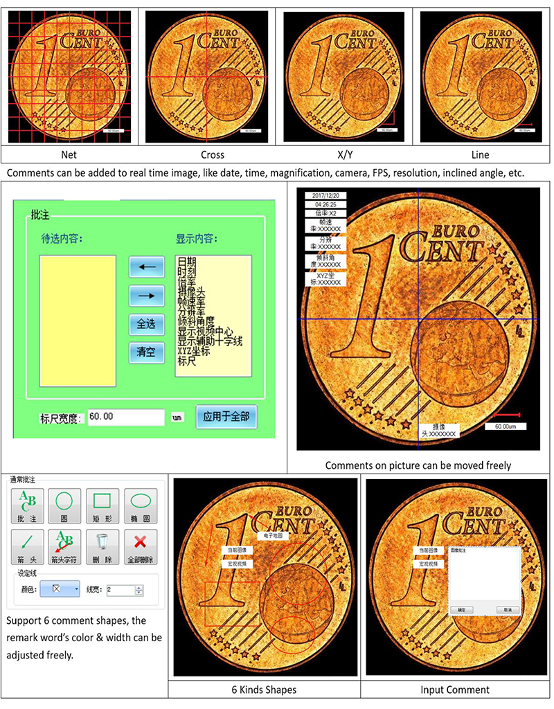
| Free Comments The comment information can be freely inserted and displayed in the microscope camera window and 2D map window. The annotation content, ruler, color, line, etc. can be freely set, and output to the experimental report with the image |
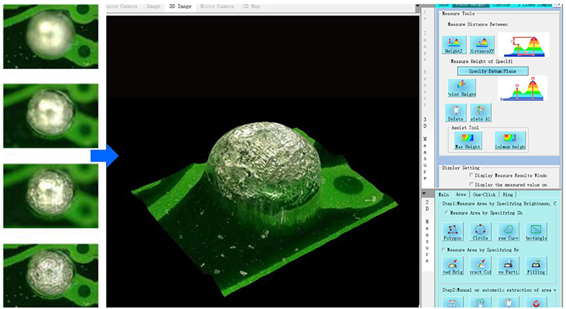
| 3D Stitching 3D stitching mode can automatically focus on uneven objects, take pictures at different heights, obtain a full-frame clear 2D image composed of all clearly focused images, and stitch all focused image together to form a 3D image, and retain all the 3D measurement data of the observed object |
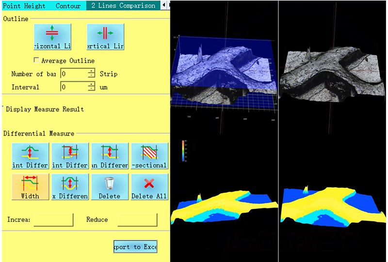
| 3D Image Comparision Two 3D images can be opened at the same time, synchronously rotated, zoomed in and out, compared and analyzed, and the comparison results such as height difference and shape difference can be automatically displayed through color identification |
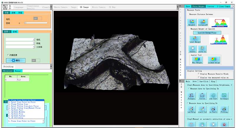
| 3D Image View The saved 3D image can be opened at any time, controlled by the mouse to rotate freely, zoom in and out, open the ruler, color identification and other auxiliary tools, which is convenient to visually observe the 2D surface shape and 3D structure of the object from any angle |
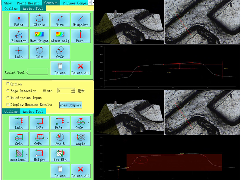
| 3D Measurement 3D image also saves all the three-dimensional measurement data of the observed object, and supports any measurement of the observed object later, including the height, depth, length, roughness, convex area, concave area, convex volume, concave volume, etc |
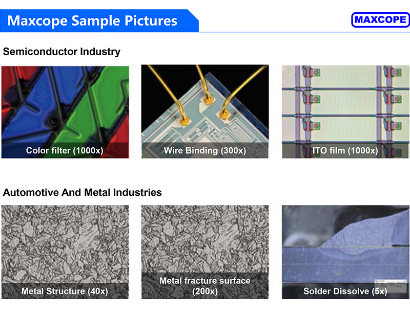
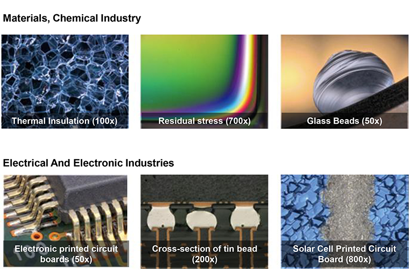
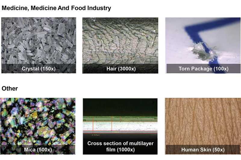
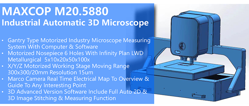
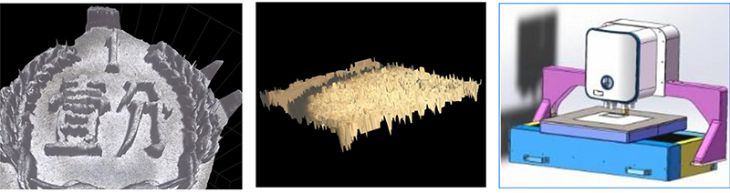

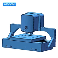
| M20.5880 Gantry Type Industrial Automatic 3D Microscopic Scanning Measurement System | ||
| Main Body | Size | 1050X450X690mm |
| Weight | 86kg | |
| Nosepiece | 6 Holes Coding Motorized Nosepiece | |
| Objective | Infinity LWD 2x, 5x, 10x, 20x, 50x, 100x | |
| View Method | Transmit / Reflect LED, Polarizing (Optional), DIC (Optional) | |
| LED Life Time | 40000 Hours | |
| XY Motorized Stage | Repeatability | 15um (Standard), 3um (Optional) |
| Moving Speed | 12mm/sec (max) | |
| Moving Range | 300x300mm | |
| Stage Size | 550X570X65mm | |
| Stage Load | 10kg | |
| Round Stage | 360° Rotatable, 30° Incline Angle Adjustable (Optional) | |
| Z Motorized Control | Auto Focus | Auto Focus Speed 0.3 Second (Fastest),Normally 1-3 Seconds |
| Z Resolution | 0.1um | |
| Moving Speed | 20mm/sec(max) | |
| Moving Range | 100mm | |
| Micro Camera | Digital Camera | 20MP 1"CMOS USB3.0 High Speed Digital Camera |
| Resolution & FPS | 15@5440x3648 50@2736x1824 60@1824x1216 | |
| Marco Camera | View Field Up To 70mm * 90mm, Resolution 0.2mm (Optional) | |
| Computer | HP | i7 128G 256G+1T SSD/ NVMe, 2G Graphic Card, 27"Monitor |
| Software | Maxcope | 3D Version, Detail See Maxcope Software Version Table |
| Image Format | Output | JPEG,TIFF |
| Other | Voltage | 110-220VAC,60/50Hz |
| Power Supply | 80W | |
| Working Temp. | 10°~38°C | |
| Working Humidity | 10%~90%(No Condensation) | |
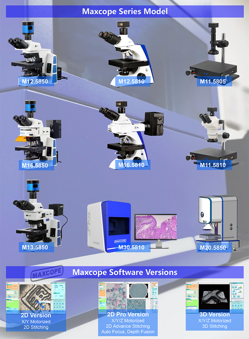
| Maxcope Software Version Table | |
| 2D Version | |
| (For XY Motorized Model) | |
| XY Motorized Control | Control the motorized stage through software, support one-click set/return to origin point, three control methods: |
| • Click the 8-direction arrow with the mouse to manually control the stage movement, and the step distance and move speed can be freely stetted | |
| • Long press the mouse and drag in the camera preview window to control the electric platform to move in the corresponding direction | |
| • Double-click the mouse at any point in the preview window, you can control the electric platform to move the double-click point to the center of the window for display | |
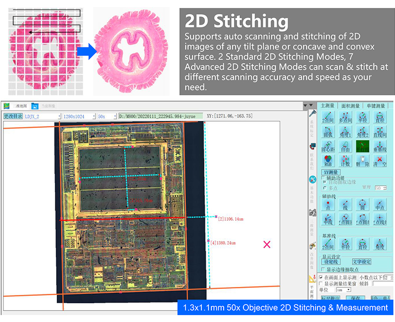
| 2D Stitching | 2 Standard 2D Stitching Modes: |
| • Plane Scan Point by Point, high precision, slow speed | |
| • Plane Flying Scan, low precision, high speed | |
| Supports automatic scanning and stitching of 2D images at any magnification, with optional scanning accuracy and speed. | |
| Free Stitching Area | Provides 6 stitching area modes, which can quickly set stitching areas of any shape: Polygon, 2-point rectangle, 3-point circle, 4-point ring, outline, free curve. |
| • Outline mode can automatically detect the edge contour of the object as the stitching area. | |
| • Free curve mode can freely draw any shape as the stitching area. | |
| 2D Stitching Optimize | The built-in advanced algorithm can intelligently optimize and correct the grid phenomenon and shadow phenomenon caused by lens aberration, uneven lighting and other factors when scanning and stitching, so that the stitched image will be one high-definition, no offset, no grid, no shadow. |
| Calibration | It can do the necessary calibration before measurement, for different camera & objective lenses, user can add, delete, and manage the calibration list at any time |
| 2D Measurement | 2D plane measurement 10+ functions, including length, angle, radius, diameter, free curve length, parallel line distance, point-line distance, 2-point distance, multi-point distance, radius, diameter, arc length, RGB measurement, counting, etc.,and a variety of auxiliary lines and reference line tools are provided. Combined with these tools, various complex measurements can be achieved, and various measurable information of planar images can be obtained more efficiently. |
| 2D Map Guide | After scanning and stitching to generate a panoramic image, it can be used as an electronic 2D map for navigation. Click the 2D map to control the motorized stage to quickly locate the specified position for high-magnification observation, avoiding the confusion of difficult positioning in traditional high-magnification observation. |
| Point of Interest | Click the mouse to freely set and save multiple points of interest on the image, you can select and quickly return to the point of interest at any time for repeated focus observation |
| Marco Camera Guide | The model with optional macro camera, the panoramic image previewed in real time can be used as an electronic 2D map for navigation function, one click can reach the point of interest for high-power observation |
| Motorized Nosepiece | Optional motorized nose wheel models, you can select different objective lenses in the software, and switch the magnification with one click |
| Motorized Illumination | The model with optional illumination control, can be manually adjust light brightness in the software, or use the automatic lighting function to easily get the best lighting effect, |
| Screen Split | 2 split windows can be set to observe and compare multiple images at the same time |
| Free Comments | The comment information can be freely inserted and displayed in the microscope camera window and 2D map window. The annotation content, ruler, color, line, etc. can be freely set, and output to the experimental report with the image |
| Full Parameter Record | While taking pictures and videos, software can automatically records comprehensive information such as shooting date, objective lens, magnification, stage position, etc., which is convenient for outputting to experimental reports or for reproducing observation results later. |
| Extra Long Video Record | The longest 1 hour, the fastest 50PFS video recording, can comprehensively record the experimental detection process, or the long-term change process of the observed object, subtle movements and other information. The video results can be fast-forwarded or played frame by frame, and still images can be extracted and saved. |
| Customrize Report | Freely set Word and Excel report templates, including images and comprehensive shooting parameters, which is convenient for quickly outputting a complete inspection report in the later stage |
| Free Interface | The software interface and each submenu can be freely settled by dragging and dropping with the mouse, and can be saved, exported, and imported into the customized interface layout, and the default simple interface can also be restored easily by hot key Ctrl + G. |
| Multi Language | The software supports Simplify Chinese, Traditional Chinese, English, Russian, Korean, Japanese, Iranian, Dutch, French, German, Italian, and other language versions can be customrized. |
| 2D Pro Version (2D + Below Functions) | |
| (For XYZ Motorized Model) | |
| Z Motorized Control | The software controls the Z-axis motorized lift, support professional functions such as manual focus/auto focus/super depth of field fusion |
| • Click the up and down arrows with the mouse to manually control the Z-axis lift and focus | |
| • One-click autofocus, focusing speed & accuracy can be selected | |
| 2D Advanced Stitching | 7 Advanced 2D stitching modes, combined with Z-axis motorized, can perform auto-focusing with various speeds and precisions on inclined planes and concave-convex surfaces to scan and stitch into a full-frame clear 2D images, especially suitable for complex industrial inspection, special slice observation, etc. |
| • Bevel Scan Point by Point | |
| • Bevel Flying Scan Manual Focus | |
| • Bevel Flying Scan Auto Focus | |
| • Up/Down Fast | |
| • Up/Down Middle | |
| • Up/Down Fine | |
| • Up/Down Fusion | |
| Auto Focus | One click autofocus, as quick as 0.3-2 seconds for each focus, focusing accuracy and speed are optional |
| Depth Fusion | The innovative design of high-quality depth synthesis can easily do 200~500 layers of super depth of field superposition and fusion in a short period of time. The software makes intelligent judgment on abnormal high and low points, scans with full coverage, and obtains full-frame clear focus pictures |
| Auto Edge Selection | When the measurement point manually selected by the mouse is deviated on the screen, the software can automatically detect the edge of the target and automatically correct the measurement point to the edge to eliminate human error and improve the efficiency of measurement range selection |
| 3D Version (2D Pro + Below Functions) | |
| (For XYZ Motorized Model) | |
| 3D Stitching | 3D stitching mode, which can automatically focus on uneven objects, take pictures at different heights, obtain a full-frame clear 2D image composed of all clearly focused images, and stitch all focused image together to form a 3D image, and retain all the 3D measurement data of the observed object |
| • 3D Stitching | |
| 3D Image View | The saved 3D image can be opened at any time, controlled by the mouse to rotate freely, zoom in and out, open the ruler, color identification and other auxiliary tools, which is convenient to visually observe the 2D surface shape and 3D structure of the object from any angle, and thoroughly and clearly understand the observed object |
| 3D Measurement | The 3D image also saves all the three-dimensional measurement data of the observed object, and supports any measurement of the observed object later, including the height, depth, length, roughness, convex area, concave area, convex volume, concave volume, etc. |
| 3D Image Comparision | Two 3D images can be opened at the same time, synchronously rotated, zoomed in and out, compared and analyzed, and the comparison results such as height difference and shape difference can be automatically displayed through color identification |
| Multi Files Comparison | Multiple files can be opened at once for cross-section, volume, area, flatness, roughness measurements, and more. Even if there are multiple evaluation samples, analysis can be performed instantaneously under the same conditions. It is possible to see at a glance where and what differences exist, such as changes in shape due to prototypes with different manufacturing conditions or wear. Not only can measurement work be significantly reduced, but evaluation errors caused by deviations in measurement conditions can also be prevented.。 |
| Optional Function Module For Special Observation | |
| HDR | Acquires multiple ultra-clear images using a single wavelength of light and images with different shutter speeds, and turns them into 1 image with high grayscale data. Achieved unprecedented high-definition, high-contrast observation |
| DIC | The automatic turret of the six-hole objective lens, combined with the adjustment of the DIC prism, can make the height difference of the objective lens surface produce obvious relief effect, greatly improve the contrast of the image, and facilitate the user to analyze efficiently and accurately. |
| Combined with polarized light observation, DIC can reflect the smallest surface morphology differences as brightness differences, and can display perfect images even for low-contrast, multi-phase samples and reflective materials. | |
| Metallurgical Analysis | Using automatic image stitching, the image is analyzed through image enhancement, contrast adjustment, scratch processing, image correction, multi-region image segmentation, morphological processing, image annotation, and layer merging processing methods. It is easy to use and concise, and the measurement is accurate and reliable. |
| Grain Size Analysis | According to JIS standard G0551 or ASTM standard E1382, the measurement line can select [vertical line], [horizontal line], [diagonal line], [multiple circles] to measure the crystals on test line. |


 Huang Xin