 English
 Pусский
 Français
 Español
 Portugues
 Deutsch
 lingua italiana
 العربية
 Melayu
 Filipino
 Монгол хэл
 dansk
dansk Bahasa indonesia
 日本語
日本語 한국어
한국어 Türk dili
 Tiếng Việt
 svenska
 Nederlands
 Norsk språk
|
What Is Atomic Force Microscope?
|
||
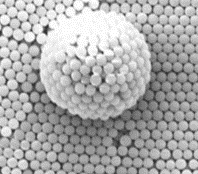 |
Scale: 1mm=100oum=1,000, 000nm Naked eye 0.15-0. 3mm Compund Microscope 200nmSEM 1-3nm TEM 0. 2nm AFM 0.05-0. 2nm |
 |
 |
||
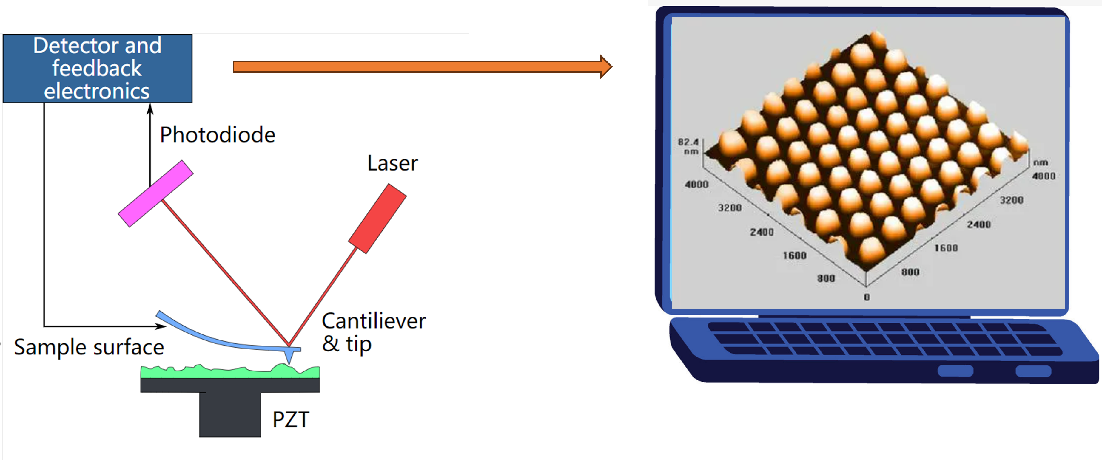
| An AFM generates images by scanning a small cantilever over the surface of a sample. The sharp tip on the end of the cantilever contacts the surface, bending the cantilever and changing the amount of laser light reflected into the photodiode. The height of the cantilever is then adjusted to restore the response signal, resulting in the measured cantilever height tracing the surface. Surface imaging is achieved by detecting the interaction force between the tip and the sample, whether it is conductive or not. The information is gathered by "feeling" or "touching" the surface with a mechanical probe. The surface topography is commonly displayed as a pseudocolor plot. |
||
|
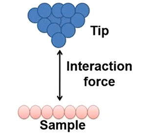
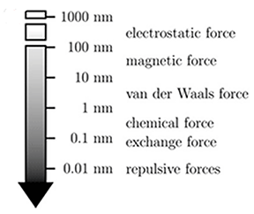
How Works? ——Forces |
|
 |
 |
|
In AFM we are keeping our probe close to surface and moving the surface underneath our probe.
Those Van der Waals forces are going to vary as the topography of the surface brings the surface closer to the tip and further away.
|
|
|
How Works? ——Positioning
The AFM tip moves over features of different height the deflection of the AFM cantilever changes. Attractive (repulsive) tip-sample forces bend the cantilever towards (away) from the sample. This deflection is tracked by a laser beam reflected from the back side of the AFM cantilever and directed into a position sensitive photodetector (PSPD). Data is transmitted to a feedback system.
|
|
How Works? ——Feedback system & Imaging
A feedback loop controls the vertical extension of the scanner in order to maintain near-constant cantilever deflection and hence a constant interaction force. The coordinates that the AFM tip tracks during the scan are combined to generate a three-dimensional topographic image of the surface.
|
|
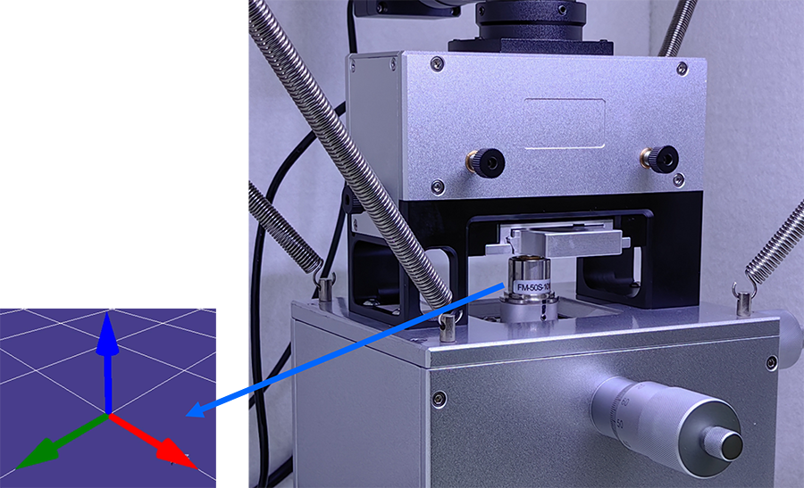
How To Realize Motion On XYZ Directions?
 |
|
How Works? ——Piezoelectric Tube Scanners
Piezoelectric tube scanners are thin cylinders of radially poled piezoelectric material with four external electrodes and a continuous internal electrode. When a voltage is applied to one of the external electrodes, the free end of the tube will bend towards the applied voltage.
The Z axis is a single element that expands and contracts to move the tip up and down.
Tiny moves to achieve XYZ moves
So feedback system is most important in the AFM. 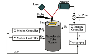 |
|
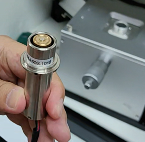
Piezoelectric Ceramics
- Convert electrical energy into mechanical motion -Move either the probe or sample in 3 dimensions
- Have very precise motion control(<0.01 nm)
|
|
 |
|
|
|
|
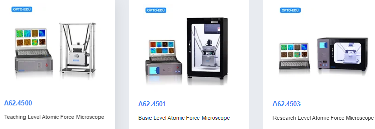
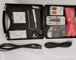
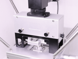
OPTO-EDU MODEL A62.4503 AFM
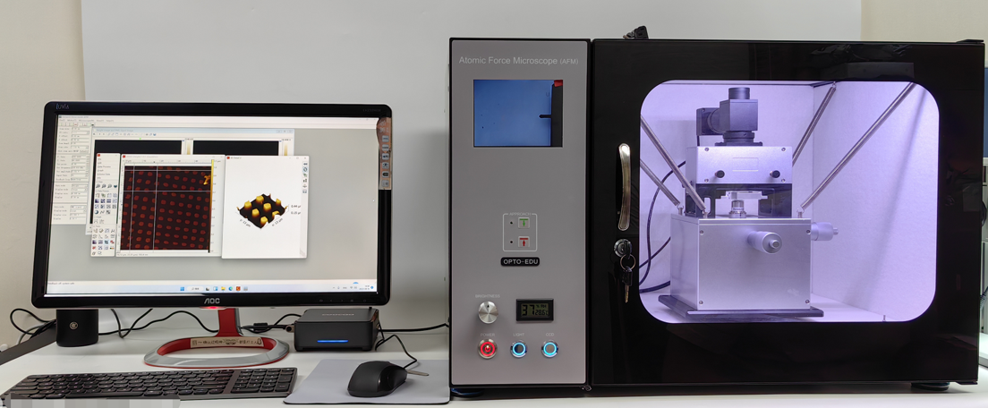 Main Component 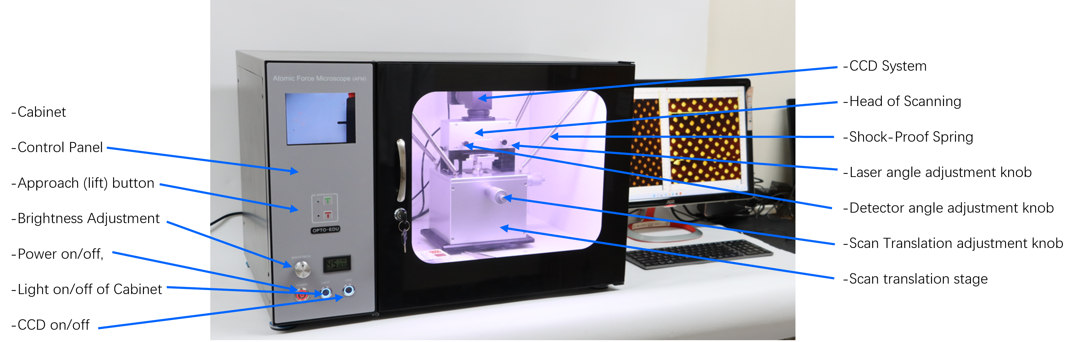 |
|||
 |
 |
 |
 |
|
Software Installation
|
|||
|
1. Install software driver
2. Reset the COM Port Number to COM3 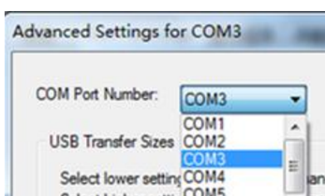 |
 |
||
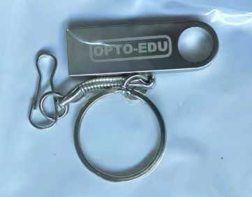
| 3. Install the AFM operation software: Copy the file “AFM software” to PC, then open the file “TAFM” to delete the configuration document “TAFM.ini”. Double click the “TAFM.EXE” to open it and operate. The contact mode AFM software is installed and open in the same way as the tapping mode one. 4. Offline software Installation:Open the offline software file in CD, double click “ WSxM.exe” to install it following the hint until it is finished. |
|||
|
Tapping AFM Operation Method
Step 1: Turn on the main power of AFM, then Open “TAFM” file, double click “TAFM.exe” to enter tapping mode AFM software interface.
|
|
|
Step 2: Choose the scan resolution. Choose 512
Step 3: Electronics calibration. Step 4: Adjust laser and Position sensitive detector. |
|
|
Step 5: Search resonance frequency.
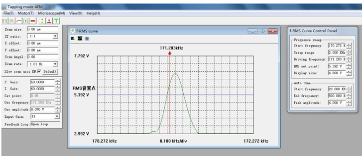 Step 6: Select system parameter.
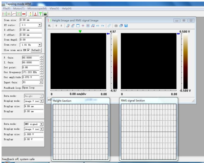 Step 7: select image color
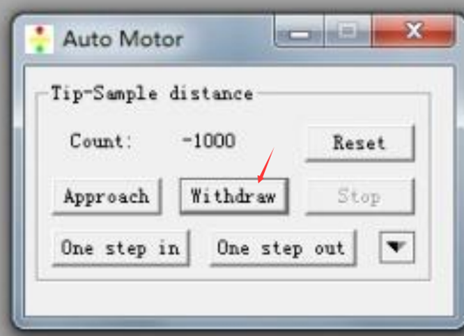
Step 8: tip – sample approach Step 9: Observe the RMS-Z curve. Step 10: image scanning. 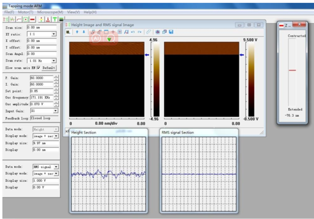 Step 11: Withdraw tip, shutdown AFM.
 |
|
|
Contact Mode AFM Operation Method
Step 1: Double click “AFM.exe” file to enter contact
Step 2, 3, 4, 5, 6 : Just the same as those of Tapping mode AFM step 2, 3, 4, 6, 7. ( NO STEP 5). Step 8: tip – sample approach: Before approaching, set the “set-point” as -1~0.9 V, Step 9: Observe F-Z curve. Step 10, 11: It is the same as that of tapping mode AFM |
|||
|
|
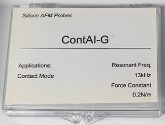
Before starting Contact Mode AFM operation, Contact Mode Probe must be fitted
 |
||
|
Can Map Potential, Other Electron Properties, Friction etc.
|
|
|
In Scanning
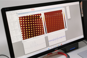
Now we see the topography of the surface showing up on our screen |
Image Generation
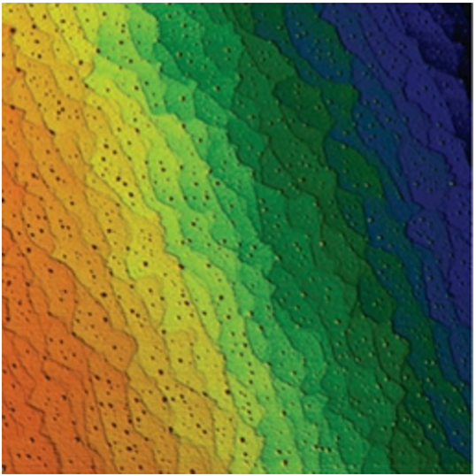
Topographic Pseudocolor Plot |
|
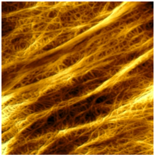
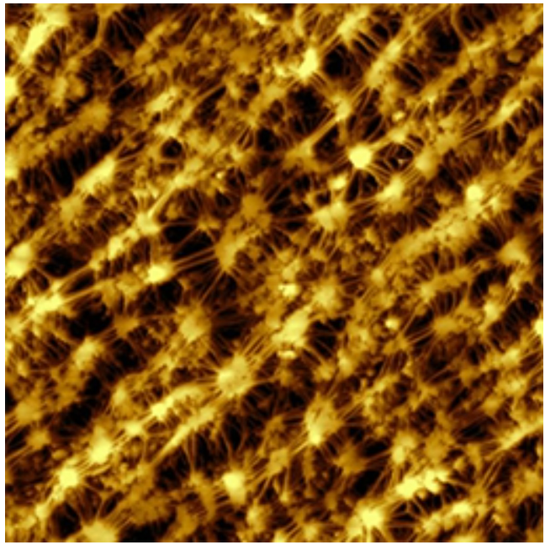
Sample Image
|
|
 |
 |
|
PE Film
|
STO Film |
 |
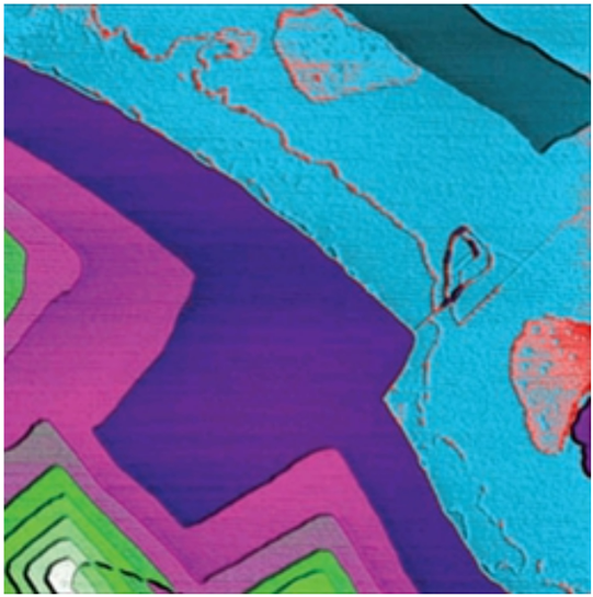 |
|
Teflon
|
Multilayer Graphene |
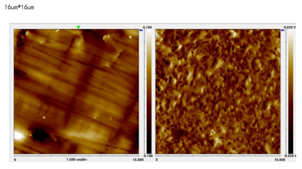 |
|
|
Permanent Magnet
|
Morphology & Phase |
 |
|
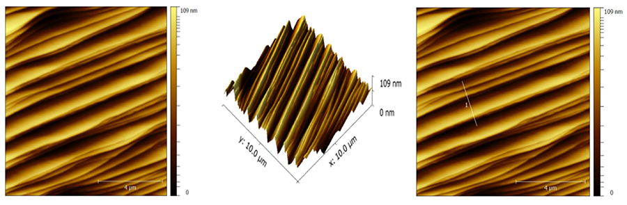
| 2D, 3D, Z Value | |
|
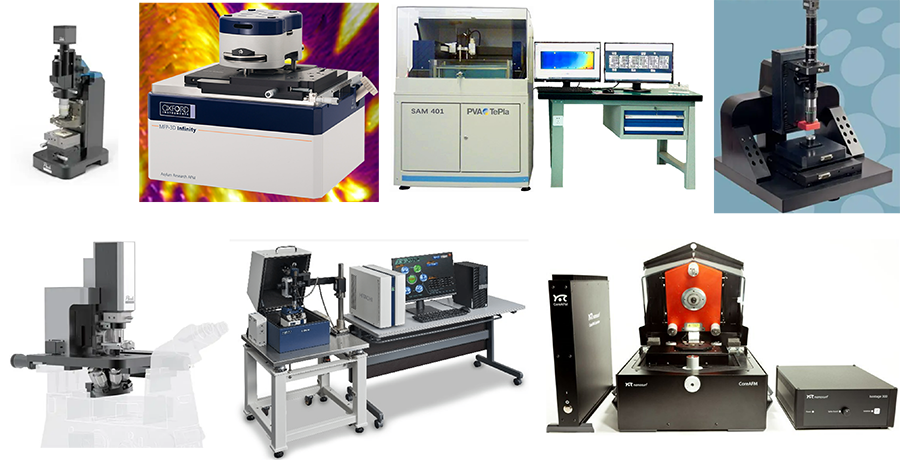
All are AFM
 |
|
For any further questions or inquires about fluorescent microscopes, you are welcome to contact us at [email protected]. We will be happy to assist in selecting the Best Suit model! |
 |


 Huang Xin